This is how I learned ->
http://imrannazar.com/GameBoy-Emulation-in-JavaScript:-GPU-Timings
http://imrannazar.com/GameBoy-Emulation-in-JavaScript:-Graphics
I'll try to elaborate as best as I can. The GB's LCD draws graphics scanline by scanline. It starts at the top (Line 0) and works it's way from left to right, top to bottom, until it reaches the last visible scanline. When drawing an individual pixel, the GB will look up which tile it needs to draw and the relevant palette data of the tile data. On real hardware, the LCD needs time to jump from the right-most pixel at the end of a scanline (pixel 159, Line 0) to the next scanline, first pixel (pixel 0, Line 1). This period is called Horizontal Blank or HBlank for short. Ignoring mid-scanline rendering (it is a fringe case, don't worry about it) In terms of drawing data to the screen in an emulator, this is the relevant time to render a scanline's pixels, since on real hardware HBlank basically says "Hey, we're done with this scanline, let's move on." The GB hardware is very precise, like most computers; HBlank will after a specific amount of CPU cycles have happened, so you'll always know when your enter HBlank as long as you keep track of that.
The GB has what's called Tile Maps, which are basically 1-byte entries that point tiles. The GB's VRAM can hold two Tile Maps, each with a size of 32x32 tiles (tiles themselves are always 8x8, the BG size is 256x256 altogether). The Tile Maps would look something like this in hexadecimal:
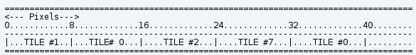
In which case each byte represents a tile number (Tile #1, Tile #0, Tile#2, Tile #7, you get the idea). Pretend these are the first 5 bytes in our Tile Map. If we were going to draw this, we'd need to examine the pixel data contained in Tile #1 to get the first 8x8 section of graphics, then read Tile #0 to get the next 8x8 section of graphics, and so on (hope this ASCII chart works, if not see attachment...)
Code:
==================================================================================
<--- Pixels--->
0............8.............16.............24.............32.............40........
----------------------------------------------------------------------------------
|...TILE #1..|...TILE# 0...|....TILE #2...|....TILE #7...|....TILE #0...|.........
==================================================================================
I should note that you should not draw the entire 8x8 section of the tile all at once, just the relevant line of that tile. That is to say, if the current scanline (modulus 8) is 0, draw pixels 0-7 of the tile. If the current scanline (modulus 8) is 1, draw pixels 8-15. If the current scanline (modulus 8) is 2, draw pixels 16-23, and so on. You can draw each 8x8 section at a time, but that would lead to incorrect results in a number of circumstances where Background Scroll X is changed between scanlines (used to create wave-like screen effects a la the beginning of the Oracle games, or used to properly draw the HUD in Super Mario Land). If you're curious about the reason for doing modulus 8 (% 8 in C++) let me know (it involves a bit of math) and I'll draw up a diagram to better explain it.
Anyway, in the above example, you'd first see that the Tile Map says you need to look at Tile #1 for pixel data to draw. You simply then read the data at Tile #1's memory location, determine what color the pixel needs to be based on the current palette, then draw it to the screen. Again, a gross oversimplification, but that's the gist of it. If you have any specific questions, I'll try to answer them.
 .
.