What's new

Game Boy

Shonumi

EmuTalk Member
That e-2 bit was probably Nintendo trying to encourage good program design. The JR instructions occupy 2 bytes in machine code. When performing the JR instruction, the PC is actually pointing to the instruction right after JR. If e is specified as -1, the PC would technically be the the address of JR's immediate, which would then become an opcode the next cycle, which could lead to some wacky code execution. It's probably perfectly legal to do what I described above, but Nintendo probably didn't want to have games messing up, so they opted to keep programmers safe to begin with.

So what I think they meant to explain was that the signed immediate (e) should always be calculated as the value you want to jump first, then subtract 2. So if you wanted to jump the PC to one byte before the JR instruction, you would not use -1 (that jumps the PC into JR's immediate) but -3. This concept is poorly communicated in Nintendo docs though, and it took me some head-scratching to figure out what they meant.
 

Rüdiger

New member
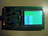
I ported my emulator to the STM32F429I-Discovery board,
which has a 180MHz Cortex-M4 with 256KB RAM and 2MB flash, a 320x240 LCD and 8MB SDRAM.

It runs but it's very slow, I guess single-digit FPS. There is no input, no sound and the
game has to fit inside the flash together with the emulator.
The board can be programmed and debugged over usb, which makes things considerably easier,
but programming larger files doesn't work reliably and anything over 1MB almost always breaks :( .

Next up are input and some missing rendering stuff.
Getting acceptable performance will probably not be as easy and I may have to rewrite the critical
parts in assembly. It really shows that I did not write the code with speed in mind :down: .
 

Attachments

  • CIMG8588_s.JPG
    CIMG8588_s.JPG
    326.3 KB · Views: 1,949

Shonumi

EmuTalk Member
Hey, that's very cool :)

The closest thing I ever did was port my emulator to the Dingoo A320 a long time ago (400MHz MIPS CPU). I must admit though, 180MHz seems awfully limited, you'd have to make every cycle count. ARM assembly is pretty easy to get to grips with, and implementing the GB's CPU instructions in assembly shouldn't be that difficult. Any big plans for your STM32F429I-Discovery board?
 

sebi707

New member
After seeing your emulator on the STM32F429I-Discovery board I just had to register here because currently I'm working on a very similar project. First I started about 10 months ago to create my own Gameboy emulator with a friend. The basics were working very quickly but getting every minor detail of the Gameboy hardware right is very time consuming. I also wanted to port our emulator to a microcontroller and after the first failed attempt to use a 32 MHz ATxmega we switched to the STM32F4-Discovery Board with a 168MHz Cortex-M4 and 192 KB RAM. The emulator is supposed to be a full gameboy color emulator. Currently the emulator already runs twice the speed of the real gameboy but with disabled rendering and in normal speed mode. With rendering enabled (currently not very optimized) we are at ~70% of the real speed. The emulator is written in C++ and is currently not using assembler to improve performance. Instead we try to be very clever and only do work when it's absolutely necessary.
 

Rüdiger

New member
Too much work and no motivation and therefore no progress. I added SGB borders back in but that's about it.
[MENTION=111905]sebi707[/MENTION]: that sounds promising. What are you using as display? I also have the STM32F4-Discovery lying around, but never did anything useful with it.

I did some profiling on the PC version of the emulator with Zelda DX, the values are the percentage of the total execution time:
CPU: 18%
Video: 52%
Sound: 24%

Memory access is at 4.5% for reading and 0.6% for writing, so that is better than expected. (Or everything else is just much slower.)

Sound is disabled on STM32 so optimizing video seems to be the best bet. The current code uses a brute force approach and should allow for some speed gains.
I was a bit surprised to see that SDL2 spends about 17% of the total time with updating the display, even without vsync. The STM32 port writes directly to the framebuffer and should be faster.

Still, I'm not too optimistic that I can get reasonable speeds without rewriting most of it. Speed is probably single-digit fps, I will try to get some timing information on the board next.
 

sebi707

New member
We are using a cheap 320x240 display from china so I guess it's pretty similar to your STM32F429I discovery board. But since connecting the display to my STM32F4 discovery board is a pain in the ass and was the cause of many problems in the past few weeks we will create our own PCB with all the hardware that we need soon. On this PCB we are aiming for a VGA output but since we do not want to use external SRAM we are limited to 192KB of RAM and we might not have enough space for a full framebuffer.

Another problem that we are facing is the limited flash space. Currently ROMs are compiled into the emulator but later they are stored on external NAND flash. Since loading them from flash is not super fast we need to cache them in RAM on the STM32F4. The current cache implementation is very simple and needs further optimizations.

I just did a quick profiling of the emulator on my laptop and CPU takes about 19% of the total execution time and 80% for the video. Timer and sound are very quick since the sound engine was already rewritten for the microcontroller. Even though most sound tests fail the sound seems OK for most of the games tested so far. The video rendering is obviously the thing that needs optimizing right now. Currently its really slow because my render function renders one pixel at a time (thanks to Prehistorik Man). But I think it should be possible to render 4 pixels at a time since the CPU cannot change the video registers faster than that. The gameboy color double speed mode should not affect this since you cannot change the color palettes during rendering at all in CGB mode. But I'm not sure about other registers that might be changed during rendering. Do you guys know which registers can be changed during rendering except the BGP, OBP0 and OBP1 registers? Maybe you also know a game/demo which does this?
 

Rüdiger

New member
I measured the speed on the board: about 9 FPS for complete emulation and 19 FPS when disabling the rendering code. So no obvious place where I can get the missing speed. I have some optimizations in mind like moving the interrupt handling and the timer updates and the LCD state machine outside the main loop so they are not called after each instruction, replacing the memory access with lookup tables for the common cases and somehow rewriting the background rendering, which is the single function where most of the time is spend. But all that will require some bigger changes I'm not too keen on and if I don't get it at least 6 times at fast, I'll have a problem...

I 'only' need about 150KB of RAM but as the 192KB are not continuous, I put everything in the external RAM for the time being. But the goal is to put all lare objects in the 128KB block and stack and maybe the 'normal' heap in the 64KB block. Then, only the framebuffer would remain in the external memory (and with 300KB it is way too large for the internal memory anyway) and I could later connect an SD-card over SPI and place the ROM there too. The internal memory should also be a tad faster.

I don't know of any other games besides Prehistorik Man that change registers during rendering. I suspect some demos do, that would at least explain why they look so weird :lol: . I think only the palette registers are affected, but I could be wrong. I plan on keeping my line-by-line renderer and catch writes to those registers and then render the line up to the point where the write happened.
 

sebi707

New member
I don't have a measurement for FPS right now but I recorded a video of Tetris and Super Mario Land: (Sorry no sound because the LCD requires some pins on the STM32F4 Discovery Board that are also connected to the audio DAC)

Why do you need 150KB of RAM? My emulator requires less than 128KB at the moment and includes all the extended RAM regions of the Gameboy Color and 32KB of cache for ROM data. Also the framebuffer seems rather large. 300KB would be for 320x240 with double buffering? A single 160x140 buffer might still fit on the STM32F4 so that VGA output should be possible even if the emulator cannot keep up with the fixed VGA timing (LCD display is so much easier).

Catching writes to LCD registers and render the line up to the current cycle seems like a good idea. I might implement that soon. I also looked at the Demotronic Demo for Gameboy Color and it seems this Demo modifies the SCX and SCY registers while rendering. So I guess changing the WX and WY registers is also possible. However I'm not sure about various bits in the LCDC register.
 

Rüdiger

New member
I can at least say that your emulator runs a _lot_ faster :satisfied . That looks like an LCD with the SSD1289 or ILI9320 controller. I had one connected to my Z80, but at 6MHz one could watch him draw the pixels...

Why do you need 150KB of RAM? My emulator requires less than 128KB at the moment and includes all the extended RAM regions of the Gameboy Color and 32KB of cache for ROM data. Also the framebuffer seems rather large. 300KB would be for 320x240 with double buffering? A single 160x140 buffer might still fit on the STM32F4 so that VGA output should be possible even if the emulator cannot keep up with the fixed VGA timing (LCD display is so much easier).
150KB was probably an old value from the PC version. I'm at about 114KB for CPU, graphics and memory and then about 19KB more for SGB.
The 300KB buffer is for 320x240 with double buffering. This LCD has no own memory and instead the LCD controller in the STM32F4 constantly reads from the buffer and generates signals similar to VGA. I haven't tried to fiddle with the controller and the SGB borders take up most of the image anyway.
 

sebi707

New member
Yes right that's a display with the SSD1289 controller. My friends display uses the ILI9325. Since both displays have very different pinouts and my display was making some problems I ordered the same display my friend uses. The LCD on the STM32F429I discovery board seems really annoying but I guess there is a good driver from ST. I forgot about SGB RAM since our emulator doesn't emulate that at all.

What compiler and compiler/linker options are you using? We are using gcc with O3 (instead of Os) and link time optimization. We've found that both options increase performance by a fair amount.
 

venge

New member
sebi707 nice work. I'm not sure if you already did these things to optimize your display but I hope I can help a bit: I would consider removing any sprite sorting algorithm (if used). Since you use a pixel-per-pixel approach (yeah dat Prehistorik Man...) you should check the possibility getting SCX and SCY values from MMIO fires and also calculate the Y addresses in vram after LY increases. Also, you could render the whole line in one take, and don't give a **** about Prehistorik Man. After all it's just the intro. We tried something with a friend of mine to speed up the core. We are porting my gb emulator to ARM android (since java runs as sluggish as 20fps max), and I had that idea of creating fixed address ARM instructions for each gameboy opcode. So we've coded blocks of ARM instructions like a jump table but without the table:

0x00 : NOP, not much to say here
0x01 : LD BC,## Shifting 0x01 << 8 left becomes 0x100. So in our prefixed memory 0x100 contains instructions for LD BC,## , and our code reaches 0x1A0 where it jumps at the end. We fill ARM NOPs until 0x1FF, and next comes 0x02 gb instruction LD (BC),A corresponding to 0x200 of our memory.

I cannot give you fps results yet since we have a lot of things to do in the ASM core, but I think it should give a considerable amount of speed.

Also it's not cheating to frameskip a bit. If you find your core runs at a decent speed, and emulation is stalled due to display, you can skip a frame or two. The LCD "afterimage" fade, will mostly smoothen out 1 frameskip I assume.

edit: forgot to mention. You could precalculate a table of 256 (0-255) mods with the number 8. That is to avoid storming the cpu with mods, as you need 1 for BG and 1 for Window to get the correct vram bit.
 
Last edited:

Rüdiger

New member
What compiler and compiler/linker options are you using? We are using gcc with O3 (instead of Os) and link time optimization. We've found that both options increase performance by a fair amount.

I'm using gcc with O2 or O3, which is a tad faster. I also tried lto, but it causes the emulator to crash somewhere inside the initialization routine from the 3rd party LCD library. To make things worse, gcc does not emit debug information when using lto...
I managed to compile the library without lto and everything else with, but there does not seem to be a measurable performance difference. At least the binary is about 30% smaller.
After some small optimizations, I'm at about 12fps, so no breakthrough there either :( .
 

shutterbug2000

New member
Well, although I've only started my GB emulator, and it will be a long while before I get to this stage, I'd like to have a nice reference to look back on. I don't really see how graphics work. With chip-8, there was 1 opcode that drew to the screen. I know it's not like that for gb, so when I get to the graphics stage, I'd like to have a nice reference to look at.

Thanks!

~shutterbug2000~
 

Shonumi

EmuTalk Member
I'd advise having a look through these tutorials/wikis to get an idea of what's going on ->

http://imrannazar.com/GameBoy-Emulation-in-JavaScript
http://realboyemulator.wordpress.com/getting-started/
http://gbdev.gg8.se/wiki/articles/Main_Page

You can easily find Nintendo's Official GB Programming guide floating around (Google is your friend) as well as Pan Docs. Give both a read regarding what you want to know more about.

Regarding drawing things to the screen, there is no opcode to draw things on screen. The GB, like many other 2D consoles, uses tile-based graphics. The data sits in VRAM (Video RAM), and after a certain amount of CPU cycles, the LCD controller reads the relevant data and outputs something to the screen. This is a gross oversimplification of what's really going on, but you get the idea. Every once and a while, your emulated LCD's draw function will have to be called from the emulator itself (usually per-scanline after enough cycles have passed to draw one horizontal line, or less commonly per-pixel after enough cycles have passed to draw a single pixel).
 

shutterbug2000

New member
Thanks for the resources, but I still don't quite get drawing.
Particularly, when to draw, and, how to get tiles.
If you wanted to, a detailed explained/ some documented code would really help me.

~Thanks! ~
~shutterbug2000~
 

Shonumi

EmuTalk Member
This is how I learned ->
http://imrannazar.com/GameBoy-Emulation-in-JavaScript:-GPU-Timings
http://imrannazar.com/GameBoy-Emulation-in-JavaScript:-Graphics

I'll try to elaborate as best as I can. The GB's LCD draws graphics scanline by scanline. It starts at the top (Line 0) and works it's way from left to right, top to bottom, until it reaches the last visible scanline. When drawing an individual pixel, the GB will look up which tile it needs to draw and the relevant palette data of the tile data. On real hardware, the LCD needs time to jump from the right-most pixel at the end of a scanline (pixel 159, Line 0) to the next scanline, first pixel (pixel 0, Line 1). This period is called Horizontal Blank or HBlank for short. Ignoring mid-scanline rendering (it is a fringe case, don't worry about it) In terms of drawing data to the screen in an emulator, this is the relevant time to render a scanline's pixels, since on real hardware HBlank basically says "Hey, we're done with this scanline, let's move on." The GB hardware is very precise, like most computers; HBlank will after a specific amount of CPU cycles have happened, so you'll always know when your enter HBlank as long as you keep track of that.

The GB has what's called Tile Maps, which are basically 1-byte entries that point tiles. The GB's VRAM can hold two Tile Maps, each with a size of 32x32 tiles (tiles themselves are always 8x8, the BG size is 256x256 altogether). The Tile Maps would look something like this in hexadecimal:

Code:
01  00  02  07  00 ...

In which case each byte represents a tile number (Tile #1, Tile #0, Tile#2, Tile #7, you get the idea). Pretend these are the first 5 bytes in our Tile Map. If we were going to draw this, we'd need to examine the pixel data contained in Tile #1 to get the first 8x8 section of graphics, then read Tile #0 to get the next 8x8 section of graphics, and so on (hope this ASCII chart works, if not see attachment...)

Code:
==================================================================================
<--- Pixels--->
0............8.............16.............24.............32.............40........
----------------------------------------------------------------------------------
|...TILE #1..|...TILE# 0...|....TILE #2...|....TILE #7...|....TILE #0...|.........
==================================================================================

I should note that you should not draw the entire 8x8 section of the tile all at once, just the relevant line of that tile. That is to say, if the current scanline (modulus 8) is 0, draw pixels 0-7 of the tile. If the current scanline (modulus 8) is 1, draw pixels 8-15. If the current scanline (modulus 8) is 2, draw pixels 16-23, and so on. You can draw each 8x8 section at a time, but that would lead to incorrect results in a number of circumstances where Background Scroll X is changed between scanlines (used to create wave-like screen effects a la the beginning of the Oracle games, or used to properly draw the HUD in Super Mario Land). If you're curious about the reason for doing modulus 8 (% 8 in C++) let me know (it involves a bit of math) and I'll draw up a diagram to better explain it.

Anyway, in the above example, you'd first see that the Tile Map says you need to look at Tile #1 for pixel data to draw. You simply then read the data at Tile #1's memory location, determine what color the pixel needs to be based on the current palette, then draw it to the screen. Again, a gross oversimplification, but that's the gist of it. If you have any specific questions, I'll try to answer them.
 

Attachments

  • 1.png
    1.png
    3.2 KB · Views: 622
Last edited:

shutterbug2000

New member
That helps out lots! Thanks!
I think I know what to do now, but I just need to know how many cpu cycles it takes to reach hblank. According to the javascript gameboy emulator tutorial, it takes 204, I just wanted to verify. Also, how do you retrieve the tIle itself, not just the tile map.

~Thanks!~
~shutterbug2000~
 

Shonumi

EmuTalk Member
The tile itself is nothing more than a series of bytes at a specified location in memory. The game logic itself will handle filling in the correct bytes (the game will copy portions of ROM into VRAM, so all you need for that part is decent CPU emulation and decent memory read/write emulation). To grab the tile, you simply read the bytes at the memory location for the tiles. The GB stores tiles from 0x8000 to 0x97FF. Depending on what values certain registers have, you will either look at 0x8000-0x87FF for Tile Set #1 or it will look at 0x8800-0x97FF for Tile Set #0

Each tile occupies 16 bytes of memory, so if the GB is using Tile Set #1, and you want to grab something like Tile #9, you need to calculate its offset (0x8000 + (16 * 9)) = 0x8090. So then you need to read the following 16 bytes (0x8090-0x809F) to get the tile data.
 

shutterbug2000

New member
Ok, I need some help here. My original thought on loading a gameboy rom into memory was that it was like chip 8. Load everything into a memory array. However, with many roms being above the memory size, I came to the conclusion of it being "switchable memory banks". (Feel free to correct me.) How would I implement this? After trying to load a test rom and it crashing, it is probably this.


Also, on a side note, after looking through nintendo's official docs, I found out a way to get link cable working. Does this look good for the test rom "console" output?

System.out.println("Link console" + Character.getNumericValue(z80.memory[0xFF01]));

Thanks!

~shutterbug2000~
 

Top